Wednesday, December 21, 2011

Just when I thought I was done

I can't beleive that I am saying this but just as I am so close to being finished with this project I am getting ready to take it all back apart.  In the picture below you can see the spline shaft and the spline coupling.  This picture is after I had taken it apart and before I went in to bed that night. I took a picture so that I could remember how it all had been.  I didn't want to forget so I simply laid the coupling in place but did not put it on in the position that it was orgionaly.  It was very difficult to take off and I did not want to have to heat it up and knock it off again. 
When I put the tractor back together I put installed the coupling to a small line on the spline shaft where it looked like it was before.  But when I was assembling the transmission to the rear end I almost had it completely mated together before it engaged into the spline fit. 


As I think about it I think it would be best to check to see how long of an engagement it has before I start using this tractor as a bulldozer pounding the dirt and snow.  I don't want the spline in the rear end or the coupling to strip off.  I hope to do it all in one day before it snows on me. 

Thursday, December 8, 2011

Electrical Problem fixed

After trying to track down the electrical problems I finally found that I had grounding issues.
The bolts holding my transmission cover to the frame did not have a good connection. I guess my paint job was too good.

 I removed these bolts and used a file to remove all the rust and the paint under the bolt head. I also made sure the cover was free from paint and that the under side of the frame, where the nut mates, was free of paint .

 
I used a volt meter to track the connections all the way back to the engine and the starter.  Now it will turn over like a dream.
The repaired solenoid works great too! 

I did find one problem.  The spark plug seems to be bad.  What do you think?  Looks like I will be picking up a new spark plug tomorrow. 

Tuesday, December 6, 2011

Power King Economy Wiring Diagram Factory

I had been looking for a high quality wiring diagram to add to my site.  I could not find a good one so I sketched one up real quick.
My tractor is not wired this way.  I no longer have a rectifier or a seat switch or a clutch switch like this one. I will make a diagram and add it later showing how I hooked up my alternator.

Starter Solenoid Problems

As I started hooking the electrical system back up I had some problems.  First of all my 12V battery was very old and tested bad.  But after I got my new battery I still could not start the tractor.  I had power to the ignition switch because the head lights worked. I used my volt meter and found that all of the functions of my switch worked.
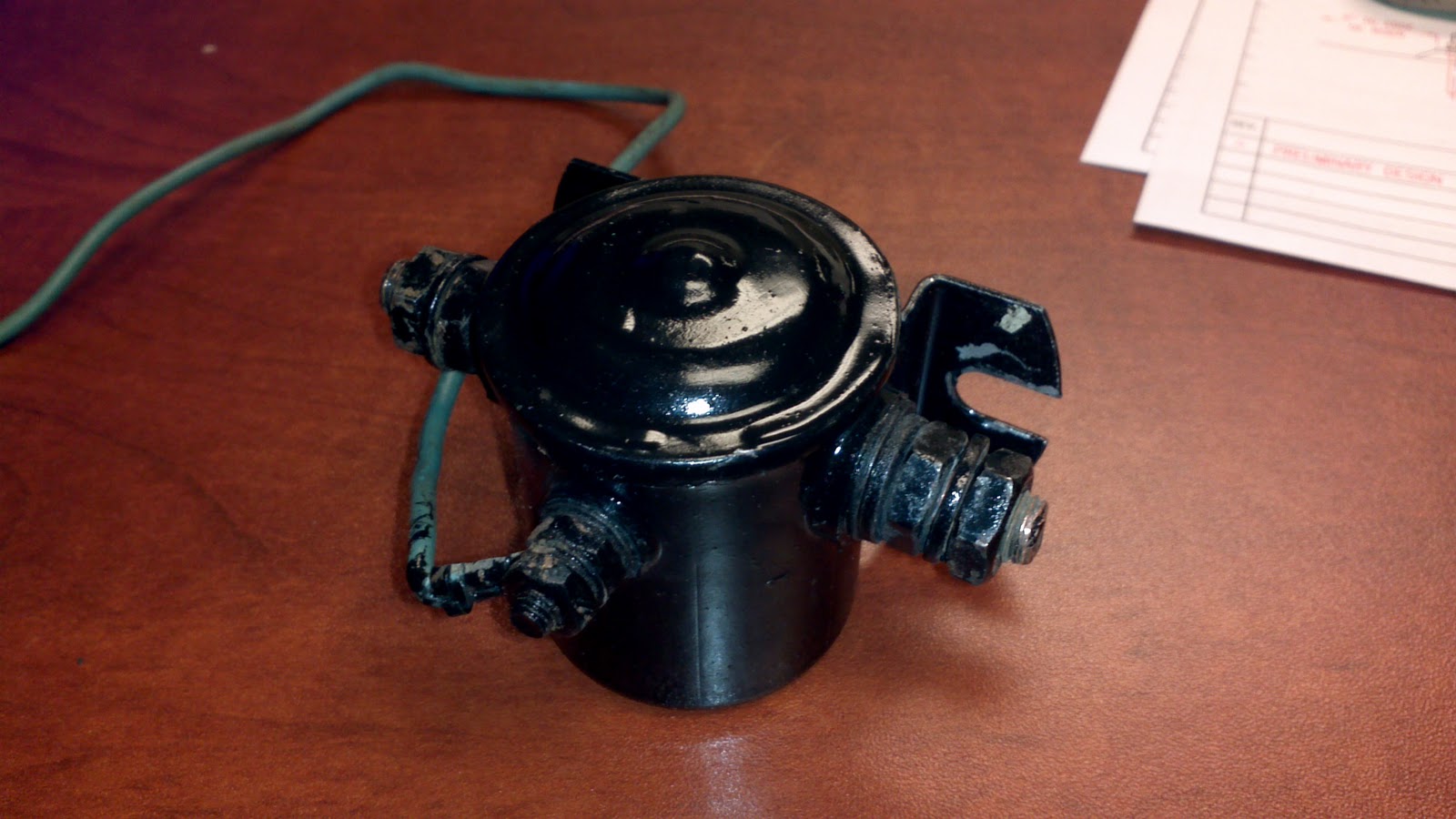
 I tested the Starter Solenoid, and what I found, I did not understand.  I had continuity between the main posts of the solenoid, which means the starter of the tractor should be energized?  Then I tested continuity between the incoming post from the ignition switch and the battery post and there was continuity.  So it was time to disassemble the solenoid to see how it was shorted.  This is what I found:
 You can see I already put some scratches in the new paint job.  Oh well, I need it to work. I can touch them up later.
 I simply use a wide flat screwdriver to pry the lid up.
 This is the top of the plunger.  The round copper disc gets pulled down and makes contact with the right and left bronze posts completing the circuit.  This is what allows current to flow to the starter from the Battery.
 The spring is to push the switch back open when the operator released the ignition switch.
 This is looking down into the plunger hole. You may notice that the disc make contact with the bronze posts in the same place every time.  When I reassemble this I will turn these around so that it has fresh surface to mate with in the future.
The post has a rubber insulating pad on the inside.
 Through the canister housing is a nylon bushing that insulates the post from the housing.
 The post that receives the current from the ignition switch is connected to the magnet wire that goes around the electromagnetic coil.  Notice that the insulating washer has been damaged from where I had turned the post around when making the external connection to the switch wire. I also found that the side posts had done the same thing.  That is why there was a short in the assembly.   
 The magnet wire was damaged and shorted against the side of the housing as well.
 I removed the insulating washer and plan to reuse it but I will flip it over to have a fresh area around the critical areas.
 This is the end of the coil wire. It simply is striped at the end and makes contact with the steel disc on the top which makes contact with the housing, which makes contact with the tractor dash to complete the circuit.
The coil did not look damaged at all so I did not take the time to rewind it.
I reassembled it careful to insulate everything to where it should be and tightened everything so that the posts will not make contact with the steel disc.  I should work now. 
Now I have another problem.  I may have fried other stuff because the starter will not do anything when I bypass everything and the lights will not work at all.  I checked all of the switches and they work.  I will keep you posted when I figure it out.  

Sunday, November 20, 2011

Install Alternator on Antique Tractor

After fighting a low battery almost every time I went to start my Power King I decided to see what it would take to install an alternator on the tractor.  I found a used Delco alternator and started figuring out how to rig it to the tractor.  At first I had a link belt on the alternator, but after a year it started coming apart.  On this tractor it is neccessary to pull the engine and cluch in order to install a belt on the middle pulleys.  The middle cluch pulley assembly has (3) pulleys to use for different equipment.  One of my pulleys is used to drive the hydraulic pump.  I am using the other for the alternator leaving the other for what every else I may need to drive in the future. 


My Dad had tried installing one in the past and had already built a bracket that was almost in the right location.  I searched the Internet to find instructions on how to install an alternator on an antique tractor and did not come up with much. So I figured it out my self.  My alternator is a self exciting alternator, which means that I have to get the engine RPM's up pretty high before it begins creating a charge to the system.  After you excite it on start up you can throttle down and the alternator will continue to work.  As I begin re-wiring the tractor, I will detail how and why I hooked it up.  I will try to make some videos demonstrating how the charging system works.


This is an updated wiring diagram of how I hooked up my electrical system to work with the Delco Alternator.  I went to my local Radio Shack store and got a few Rectifying Diodes that worked great.

Friday, November 18, 2011

Paint details soon

I have had several people wonding how I painted this tractor.  To be completly honest I had no idea how to do paint until this project.  I went to my local Pivco and they walked me through what I needed for the project.  The guys there were amazing.  They told me step by step what to do. 

I am getting ready to start painting my seat and a few parts such as my 3 point hitch and snow plow.  I will make sure that I detail every step of the process for the blog.

I bought new decals for my Power King at  http://www.serviceproparts.com/contents/en-us/d4371.html
Service PRO was really easy to buy from. Their web site was clear and professional. 

The quality of the decals are amazing.  They are a heavy duty.  They look better than what came from factory.  I can't wait to put them on.

Installing new choke cable and fabricating bracket


Ever since I can remember the choke cable on this tractor did not work. It was no big deal to me. All we had to do was; un latch the hood, open it a little, and then prop it open with the air filter cover. Then we had “easy” access to the choke lever.  After you got it started you would simply lower the hood and re-latch it on both sides. 

Well, after doing this for 25 years I decided that it would be nice to fix it properly.  The problem was I had no idea how the original choke cable was laid out and frankly, it must have not been done very well because it did not last long.  So this is what I came up with to fix the choke cable.

First of all I was very fortunate to have a good friend, Chuck, who is as big of a pack rat as me.  (He also drives a train, which is a very cool thing to say you do for a living.) He gave me a choke cable that he just happened to have laying around.  I cut it to length after I got it to where I thought it looked good. 


After I had it all hooked up I realized that there was nothing to fasten it to.  Nothing even close to where I needed to mount it. I busted out a scrap piece of 1/8” thick steel plate that I had laying in my scrap steel box and started laying out a bracket.  I used my Dewalt portable metal cutting band saw and my 19 volt Craftsman chordless drill and this is what I came up with. 
 

I put it on last night to test it out.  I still need to remove it and paint it before it becomes permanent. 

It works great! I can’t wait to start it up for the first time using my new choke cable. 


You may have noticed that I installed my freshly painted PTO.  I do not think it is on all of the way but I did not have a long enough jack bolt to take it back off.  That will be something I will look at again this weekend.

Thursday, November 17, 2011

Cleaning up the old PTO


It has been a while since I have been able to work on my Power King. Last night Rocco, my Wire Hair / Lab mix, helped me get the front PTO cleaned up.


One of the interesting features of this antique tractor is the fact that you had the ability to hook up many unique attachments to it and turn them on and off with a flip of a switch located on the tractor's dash.

The PTO on this model is an Electromagnetic Clutch assembly. When you flip the switch on the dash it completes a circuit to allow voltage to the Clutch. This voltage energizes the coils within the clutch assembly. As the magnets pull together they create fiction between the rotor of the clutch, which is keyed and bolted to the engine drive shaft, and the clutch stator which is tethered to the tractor frame. When the magnets engage, they allow the pulley to begin to spin at the same speed as the engine RPM. When the switch is turned off, it opens the circuit and an internal spring forces the clutch surfaces apart then pulleys will no longer spin.


My PTO clutch needed a little TLC. Warren, a friend of mine from Young Life, and I spent some time with some sandpaper cleaning all of the visible surfaces. I took it apart and cleaned out the dust and dead bugs (and the ones that were still alive too). After we got it looking smooth and clean we applied some beautiful Rust-oleum gloss black paint. I plan on picking up a new key this afternoon and putting it all back on the tractor tonight.

Wednesday, July 20, 2011

Front wheels

Did some cleaning and painted the front wheels. I also got the engine installed and painted. I installed a drive belt for the alternator that is too short. That means now I have to pull the engine/clutch assembly to replace it.


Some Paint going on!


Thursday, May 19, 2011

Epoxy Primer. Looking so nice.


 Last night I got back on the Power King Project.  I got the frame cleaned up and primed.  It looked awesome.  I put (2) coats of Epoxy primer.
Looking better than new.


Looking a little hazy.

Now it is time to put the kids to bed.  Tomorrow is Ethan's last day of school. 
I can't believe he will be in the 3rd grade next year!

After putting the kids to bed. I mixed me up some Hugger Orange and went to work.

I put two coats of color.  It needs 1 more.

Getting the good paint is so worth it.

Amazing.  I can't wait to start putting it all back together! 

Monday, March 14, 2011

More cleaning and Some PRIMER!

I finally got out there and was able to sand clean and and get some parts ready for primer.  I have taken some pictures of my progress and the things that I have used to primer and what I am using for paint. 
This is where the battery sits. It need lots of cleaning and sanding.

The hood need to have some dents banged out.  The guy at the paint store told me to clean it, primer it, and then use the body putty to make it smooth. 

I got the gas tank looking really nice and ready for primer.

This is all that is still together on the main frame.  I hope to take the wheels off and clean and paint with out taking this all apart.  I have degreesed it about 4 times and each time I clean more off.  hopefully only one more time. 

This joint has been broken for a long time. I welded it back up.

View from front.

Clutch housing.  The hydraulic pump is mounted here.

Hydraulic oil reservoir

This is the thinner to clean my stuff up while painting.

2 part epoxy primer that I am using.

Make life easier when mixing!  A must have!

My neighbors gun that I am using.  It works awesome! Lots of control.

The paint that I will be using.  I can't wait until it is done!

The primer went on really nice.  I wish that my paint gun held more paint.  I could only mix small amounts at a time.  I think next time I will mix lager volumes and just keep adding it as I need it. 


I also got the clutch housing primered, and the tractor dash assembly scraped, snaded and primered!  I got a lot done this weekend.  I hope that next weekend I will have some orange going on!